3. Installation
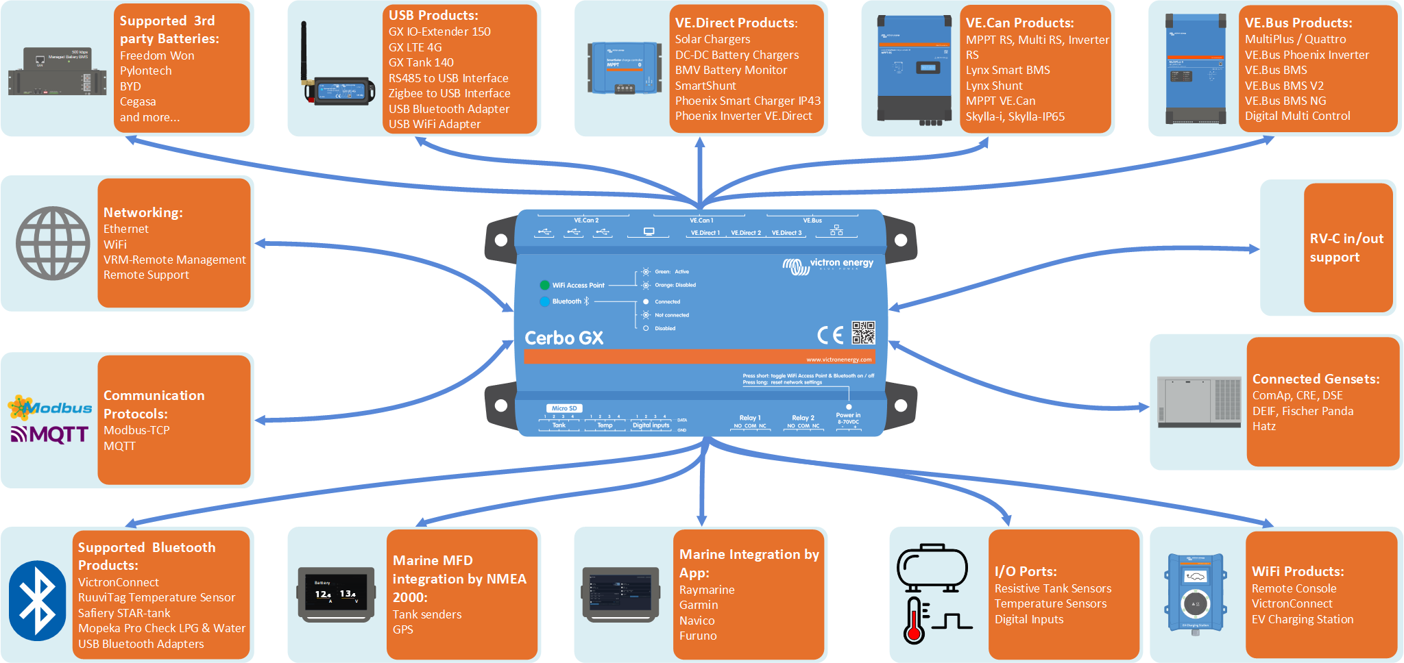
3.1. Cerbo GX (PN BPP900450100) Overview of connections
Communication ports | IO | Other |
|---|---|---|
3x VE.Direct | 4x Digital Inputs | MicroSD Card Slot (max. 32GB) |
1x VE.Can (non-isolated) and 1x BMS-Can | 4x Resistive Tank Level Inputs | Power in port (8 - 70VDC) |
1x VE.Bus | 4x Temperature Sense Inputs | HDMI port |
Ethernet | 2x Programmable Relay (NO, COM, NC - current limit: DC up to 30VDC: 6A / DC up to 70VDC: 1A / AC: 6A, 125VAC | |
WiFi 2.4GHz (802.11 b/g/n) incl. WiFi Access Point | ||
Bluetooth Smart | ||
2x USB Host ports + 1x USB Power only port | ||
The Cerbo GX supports a maximum of 15 VE.Direct devices, regardless of whether they are connected via VE.Direct ports or USB. However, this limit may be lower in complex systems, for example, those with multiple PV inverters or synchronised inverters. Always include some headroom in your system design to ensure reliable operation. | ||
3.2. Cerbo GX MK2 (PN BPP900450110 and BPP900451100) Overview of connections

Communication ports | IO | Other |
|---|---|---|
3x VE.Direct | 4x Digital Inputs (with pulse counting) | MicroSD Card Slot (max. 32GB) |
2x VE.Can (VE.Can 1 isolated) | 4x Resistive Tank Level Inputs | Power in port (8 - 70VDC) |
1x VE.Bus | 4x Temperature Sense Inputs | HDMI port |
The RJ45 sockets have been rotated 180 degrees, so its easier to take the cables out | 2x Programmable Relay (NO, COM, NC - current limit: DC up to 30VDC: 6A / DC up to 70VDC: 1A / AC: 6A, 125VAC | |
WiFi 2.4GHz (802.11 b/g/n) incl. WiFi Access Point | ||
Bluetooth Smart | ||
3x USB Host ports (fully functional) |
3.3. Mounting options and accessories
The following mounting options and accessories are available for purchase:
Please watch this video for all mounting options:
3.4. Powering the Cerbo GX
The device is powered via the Power in V+ connector and accepts 8 to 70V DC. It cannot be powered through any other connection (e.g. Ethernet or USB). The supplied DC power cable includes an inline 3.15 A slow-blow fuse.
If the DC voltage exceeds 60V, the Cerbo GX is classified as a “built-in product”. Installation must prevent user access to the terminals to comply with safety standards.
Powering with a VE.Bus BMS
When using the Cerbo GX in an installation with a VE.Bus BMS, connect the Power in V+ terminal on the Cerbo GX to the 'Load disconnect' terminal on the VE.Bus BMS. Connect both negative leads to the negative busbar or common battery negative. This is not necessary for the VE.Bus BMS V2 and VE.Bus BMS NG, as both feature a GX-Power output.
Important: Powering from the AC-out terminal of a VE.Bus Inverter, Multi or Quattro
Powering the GX device with an AC adapter connected to the AC-out of a VE.Bus device (e.g. Inverter, Multi, or Quattro) can cause a deadlock:
After a fault or black start, the VE.Bus devices will not boot because the Cerbo GX is unpowered.
The Cerbo GX cannot boot because the inverter/charger is off, causing a cycle.
Temporary workaround:
Briefly unplug the VE.Bus cable from the GX device to allow the VE.Bus products to restart.
Permanent solution:
Modify the RJ45 cabling. See FAQ Q20 for more information about this.
Recommendation:
Avoid powering the GX device from the AC-out of an inverter/charger. In the event of a shutdown due to inverter overload, high temperature, or low battery voltage, the GX device will also shut down, losing all monitoring and remote access. It is strongly recommended to power the GX device directly from the battery.
Isolation considerations
The GX device connects to various system components. To prevent ground loops, ensure appropriate isolation practices are followed. In most cases, this is not an issue, but proper system design remains essential.
Port type | Cerbo GX | Cerbo GX MK2 | Ekrano GX | Venus GX |
|---|---|---|---|---|
VE.Bus | Isolated | Isolated | Isolated | Isolated |
VE.Direct | Isolated | Isolated | Isolated | Isolated |
VE.Can | Not isolated | 1) | 1) | Isolated |
USB 3) | Not isolated | Not isolated | Not isolated | Not isolated |
Ethernet 2) | Isolated | Isolated | Isolated | Isolated |
1) VE.Can port 1 is galvanically isolated, VE.Can port 2 is non-isolated 2) The Ethernet port is isolated, except for the shield: use unshielded UTP cables for the Ethernet network. 3) USB ports are not isolated. Connecting a WiFi dongle or GPS dongle does not create any problems, as these devices are not powered by an external supply. Even when using a separately powered USB hub, a ground loop may occur. However, extensive testing has shown that this does not cause operational issues. | ||||
Extending USB Ports
The number of USB ports can be expanded using a USB hub. However, the onboard USB ports have limited power availability.
Recommendation
Always use powered USB hubs and select high-quality products to minimise issues.
To increase the number of VE.Direct devices, you can use a VE.Direct to USB adapter. Please see this document for the limit of how many devices can be attached to various different GX devices.
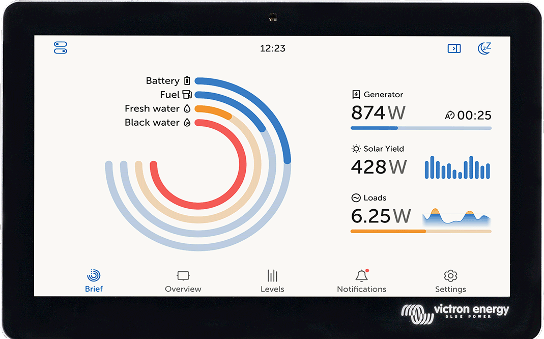
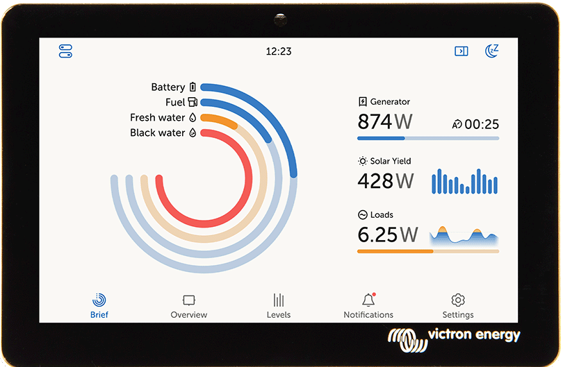
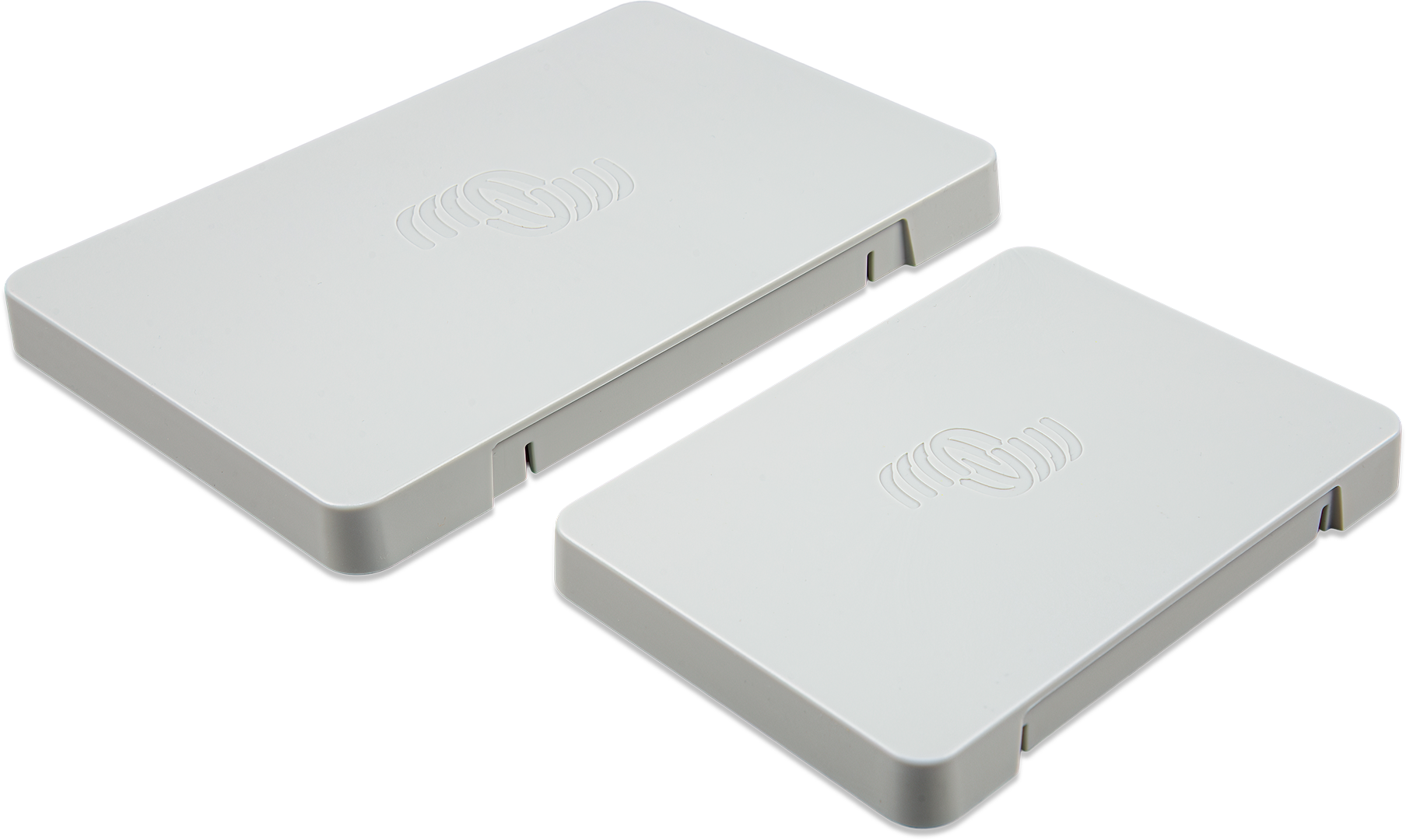
3.5. GX Touch 50 series & GX Touch 70 series
The GX Touch 50 & GX Touch 70 series are display accessories for the Cerbo GX. Available in five-inch and seven-inch versions, they offer two installation options:
These super-slim, waterproof displays provide an instant overview of the system and allow quick adjustment of settings. Their simple installation offers great flexibility when designing a clean and professional dashboard. No configuration is required. Once connected, the GX device automatically displays the system overview and menu controls. Display options Display settings are available via: Settings → General → Display & Appearance You can:
Touchscreen operation
|
 |
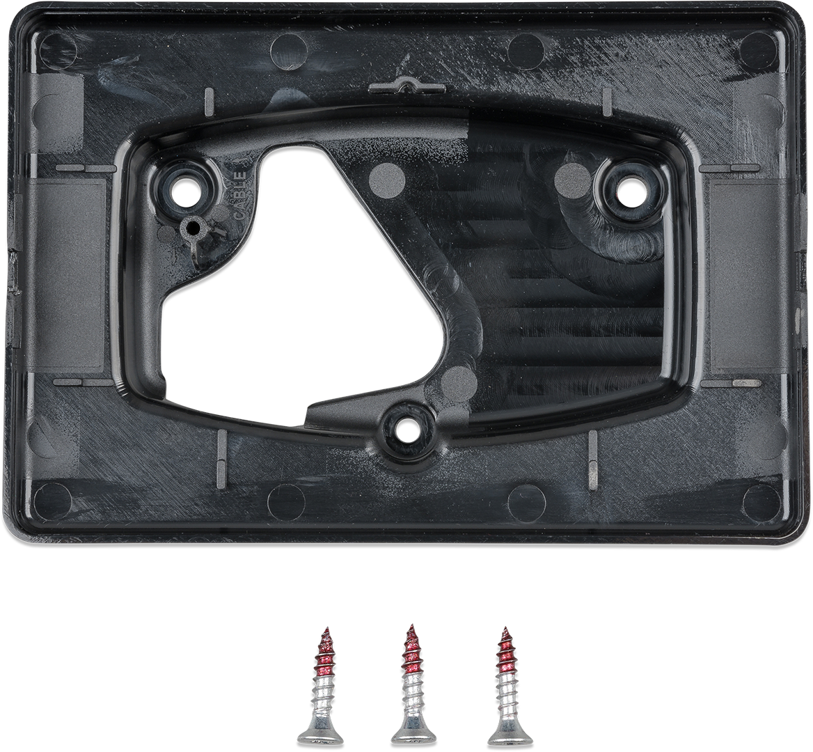
Mounting options
Depending on the model, the GX Touch can be mounted in different ways:
GX Touch 50 & GX Touch 70
Front mounting: Using the included bracket frames
Wall mounting: Using the optional GX Touch Wall Mount
CCGX cut-out adaptation (GX Touch 50 only): Using the optional GX Touch 50 adapter for CCGX cut-out.
Protection cover
A protection cover is available (included from serial number HQ2242 onwards, and also available separately, see datasheet for details). It protects the GX Touch from UV damage during prolonged sun exposure.
Note: The protection cover does not fit the GX Touch 50 Flush and GX Touch 70 Flush versions.
 |  | 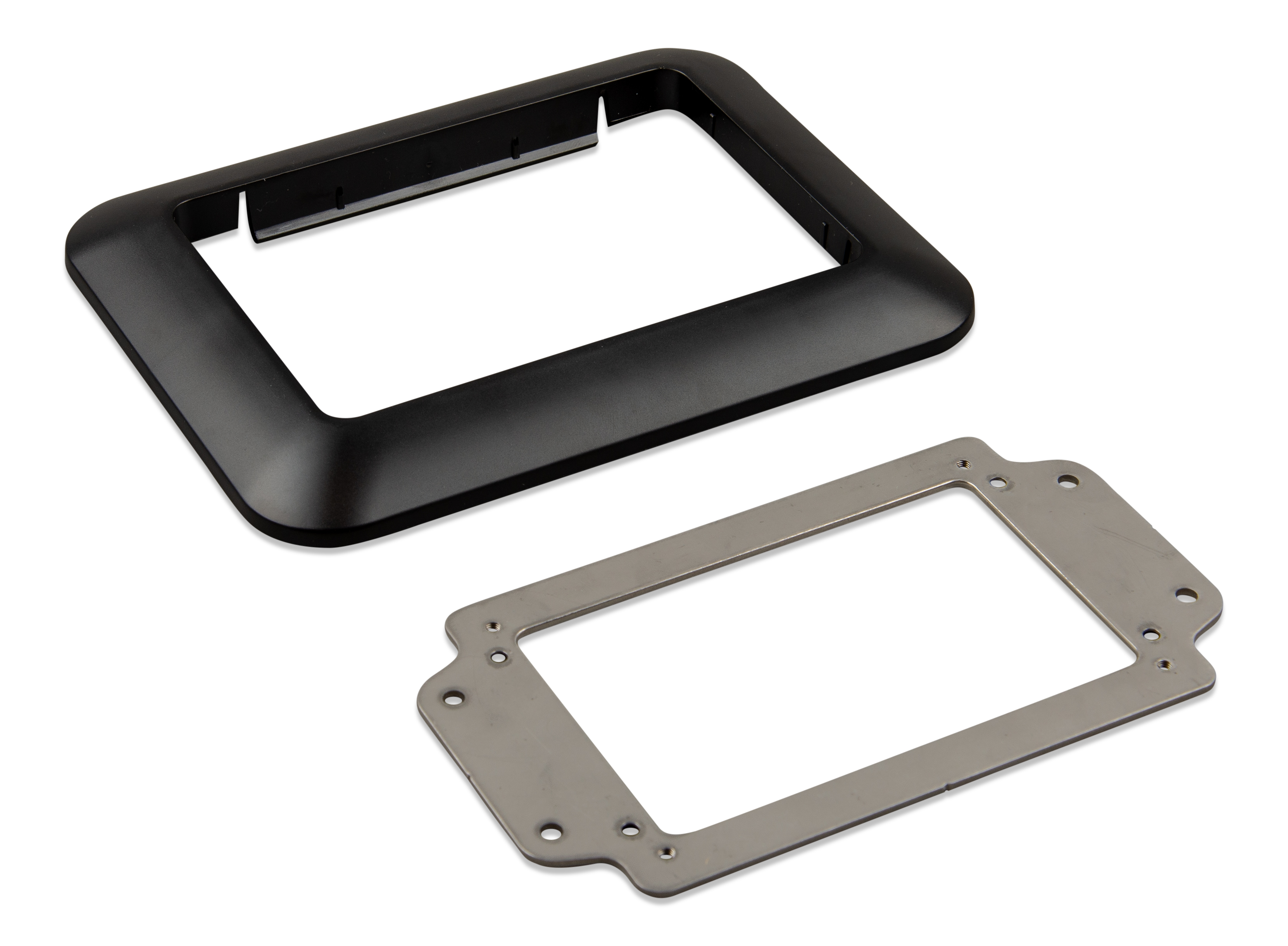 |  |
GX Touch 50 Flush & GX Touch 70 Flush
The GX Touch Flush models offer multiple flush-mount installation methods:
Flush mounting with rubber seal and brackets
Use the included rubber seal, brackets, threaded ends and wing nuts. This method provides the best dust and water resistance.
Note
Only hand-tighten the threaded ends and wing nuts
Flush mounting with adhesive
Mount directly to the underlying surface using the pre-applied adhesive. Brackets, threaded ends and wing nuts are not required. The level of ingress protection depends on the quality and flatness of the underlying surface.
Embossed (fully flush) mounting
For a fully flush finish, install according to the drilling jig dimensions. Use either the rubber seal or the pre-applied adhesive. Ingress protection depends on the characteristics of the underlying surface.
 GX Touch 50 / 70 Flush | 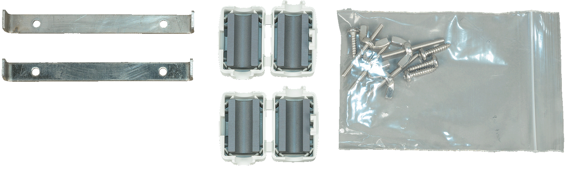 Accessories includedwith the GX Touch 50 / 70 Flush |
Connecting the GX Touch 50 or GX Touch 70
Important
Important: Connect the GX Touch to the Cerbo GX before powering it on. The recommended procedure is to unplug the power connector from the Cerbo GX prior to installation.
Connection overview
The GX Touch is connected using a single combined cable with:
An HDMI connector (for video)
A USB connector (for power)
Installation steps
Mount the touchscreen in a convenient location.
Connect the HDMI connector into the HDMI port of the Cerbo GX.
Connect the USB plug:
If you have a first-generation Cerbo GX (PN BPP900450100), connect the USB connector to the USB port located right next to the HDMI port (this USB port is only for powering the touchscreen and has no other function). If you have a second-generation Cerbo GX (PN BPP900450110 and BPP900451100), you can connect the GX Touch to any of the three USB ports.
Reconnect power to the Cerbo GX via the 2-pin Power In connector block.
After boot-up, the Remote Console will appear on the GX Touch.
Familiarise yourself with the touch display, and configure display options via: Settings → General → Display & Appearance.

3.6. Deactivating touch input control
To restrict access to the GX system, it is possible to disable touch input control for the connected GX Touch 50 or 70 touchscreen. This allows the GX Touch to be mounted visibly for the operator, while preventing unauthorised use to elevate access levels.
Note that this feature only disables touch/mouse control. On the Remote Console, you are still able to control the device with keyboard input.
There are two ways to disable the touch function of the display:
Using a momentary push button wired to one of the digital inputs
By using an external USB keyboard connected to the Cerbo GX; The touch function can then be toggled on and off by pressing the Pause/Break key.
If you wish to use this function, ensure that the USB ports and any connected USB keyboard are not physically accessible, to prevent unauthorised activation of the touch feature.
Deactivating touch input control using a momentary push button
On GX devices with digital inputs, you can configure one of the inputs to control touch functionality using an external momentary push-button.

Configuration steps
Navigate to Settings → Integrations → Digital I/O → GX Built-in - Digital input [number of the digital input]
Enable Touch Input Control
Operation
First press: Touch input is disabled.
No touch interactions are possible.
The display turns off after the configured timeout under Settings → General → Display & Appearance → Display Off Time.
Touching the screen will wake the display, but touch input remains disabled.
Second press: Touch input is enabled again.
Important: Pressing the button pulls the GPIO pin to ground. Do not apply voltage to any GPIO pins.
Deactivating touch input control using an external USB keyboard
To control touch input via an external keyboard:
Connect a USB keyboard to one of the USB ports on the GX device.
Press the Pause/Break key to toggle touch input on or off.
For keyboards without Pause/Break key use one of the substitute key combinations mentioned in this Wikipedia article.
3.7. Relay connections
The Cerbo GX has potential-free Normally Open (NO) and Normally Closed (NC) relay functionality. The relay function can be configured via the GX device menu: Settings → Integrations → Relays → Function.
Relay 1 is particularly important, as it can be used not only for manual or temperature-based triggering (as with Relay 2), but also as an alarm, generator start/stop, Connected genset helper relay, or tank pump relay.
The relays can also be controlled via the The Switch pane.
 |  |
By default, the relay is set to Normally Open (NO). The polarity can be reversed to Normally Closed (NC). Note: Reversing the polarity to Normally Closed (NC) will result in a slightly higher current consumption of the GX device.
 |  |
Important
Be sure to observe voltage and current limits of the relays as specified in the Technical specifications.