11. VE.Bus Inverter/charger monitoring
11.1. Grid Current Limit Setting
This section explains the implications of enabling or disabling user control of the Grid current limit setting, as seen in the menu Device List → [your inverter/charger]. The limit as set by the user in the Cerbo GX will be applied to all inputs where the 'Overruled by remote' setting in VEConfigure is enabled. |  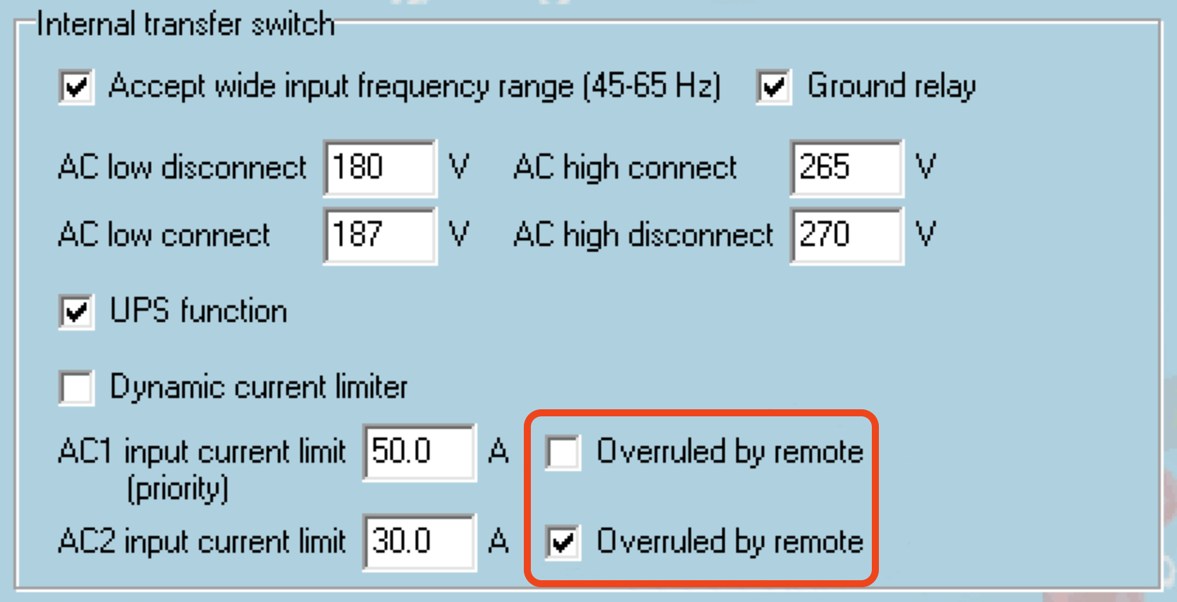 |
Example Configuration for a Boat with Two AC Inputs and a Quattro:
A genset capable of delivering 50A is connected to input 1;
Shore power is connected to input 2 (available power depends on the rating of the harbour power supply).
Configure the system exactly as shown in the VEConfigure screenshot above. Input 1 takes priority over Input 2, meaning the system will automatically connect to the genset whenever it is running, applying a fixed input current limit of 50A. When the genset is not available and mains power is present on Input 2, the Quattro will use the input current limit as configured in the Cerbo GX.
Two more examples: (In both cases, if you disable 'Overruled by remote', setting a current limit in the Cerbo GX will have no effect. And if you enable 'Overrule by remote' for both inputs, the current limit set in the Cerbo GX will be applied to both inputs.)
Minimum Grid Current Limit Values
When PowerAssist is enabled in VEConfigure, there is a minimum input current limit. The actual limit differs for each model. After setting the input current to a value below the limit, it will automatically be increased again to the limit.
Note that it is still possible to set the input current limit to 0. When set to 0, the system will be in passthrough (charger disabled).
Parallel and Three-phase Systems
The configured AC input current limit is the total limit per phase.
11.2. Phase rotation warning
The AC supply, whether from a generator or the grid, to a three-phase inverter/charger system must have the correct phase rotation, also known as phase sequence. If the phase sequence is incorrect, the inverter/chargers will not accept the AC supply and will remain in inverter mode. A phase rotation warning will be triggered in this case.
To resolve the issue, adjust the wiring on the AC input by swapping either one of the phases, effectively changing the rotation from L3 → L2 → L1 to L1 → L2 → L3. Alternatively, you can reprogram the Multi units and modify the phase assignments to match the wiring.
On the GX device, the warning will pop up as a notification on the GUI. It is also visible in the inverter/charger device menu. On the VRM Portal, the warning appears in the VE.Bus Alarms & Warnings widget on the Advanced page and will be listed in the alarm log. Additionally, an email will be sent using the VRM Alarm Monitoring system. | 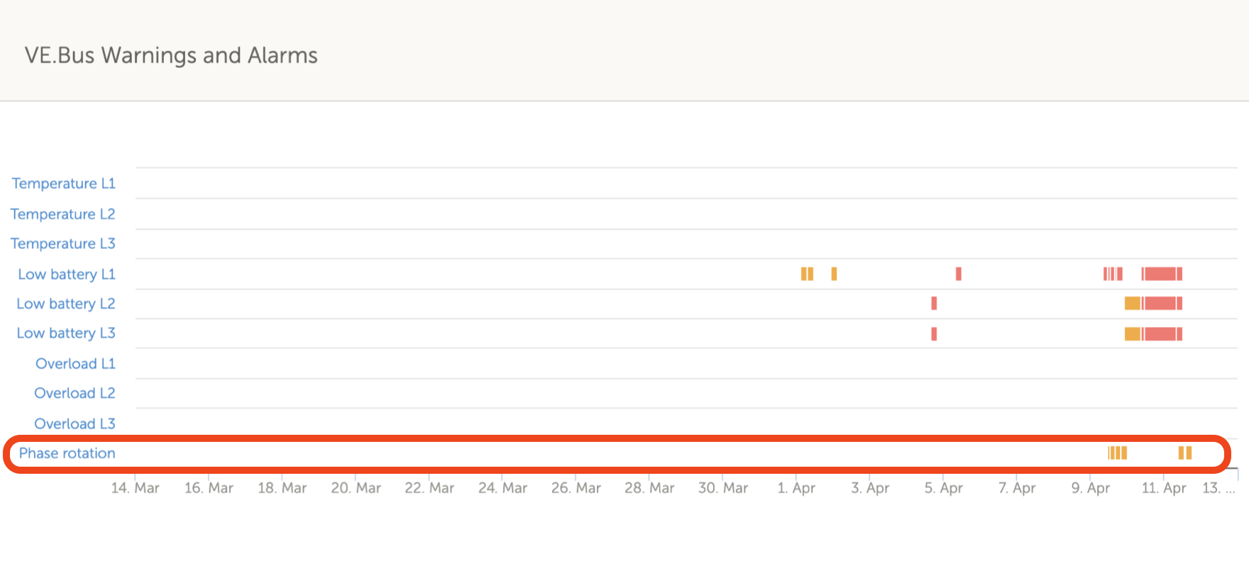 |
11.3. BMS connection lost alarm
This alarm is triggered when the inverter/charger receives CVL, CCL, or DCL data from a managed battery and subsequently loses communication with the battery or if the battery disconnects. It is also raised if the inverter/charger loses connection to the VE.Bus BMS. In both cases, the inverter/charger will shut down to protect the system. Please note that a Low battery voltage alarm may also appear. However, this alarm is not due to low battery voltage but rather a lack of information from the battery due to a communication loss. To resolve the alarm, restore the connection with the BMS or restart/power cycle the inverter/charger. A restart can be performed from the Advanced menu of the VE.Bus device. |  |
11.4. Grid failure monitoring
An alarm is triggered when this feature is enabled if the system has not connected to the AC input configured as Grid or Shore for more than 5 seconds.
|  |
Note
This setting monitors the system's connection to Grid/Shore only. Generator monitoring is provided separately through the Generator start/stop function and is not part of this setting.
Do not use this feature in systems that use the Ignore AC Input settings in our inverter/chargers: when the system ignores the AC input, ie. runs in island mode, as intended, even though the grid is available, it will report a grid failure.
11.5. Advanced menu
The Advanced menu can be accessed via Device List → [MultiPlus or Quattro] → Advanced. It contains options for equalization, re-detecting and restarting the VE.Bus system, and displays the ESS relay test status.
|  |
11.6. Alarm status monitoring
The Alarm status monitoring page can be accessed from Device List → [Multi or Quattro] → Alarm status. It displays diagnostic information on specific parameters to help with troubleshooting and provides additional information on the VE.Bus error 8/11. |  |
11.7. VE.Bus alarm setup menu
When using a VE.Bus system, you can configure the severity of issues that will trigger notifications (and an audible alert) on the Cerbo GX.
To change the VE.Bus alarm & warning notifications, proceed as follows:
When all is done, don't forget to change the access level to User when required. |  |
11.8. Device menu
The Device menu (Device List → [Multi or Quattro] → Device) offers device-related parameters such as custom name setting, firmware version, serial numbers (in the sub-menu) and more that can be used for diagnostics. |  |
11.9. VE.Bus Settings Backup & Restore
The VE.Bus Settings Backup & Restore feature allows you to save the full configuration of a Multi or Quattro to a GX device and restore it when needed.
This makes it easy to:
|  |
Backup process
The backup process works in the same way as a Remote VE.Configure download in VRM; while the backup is in progress, the GX display will stop reporting information from the VE.Bus device.
|   |
Restore process
The restore process works in the same way as a Remote VE.Configure upload in VRM. If the configuration includes assistants or settings that require a restart, the system will restart during the restore process.
|   |
11.10. Solar & Wind Priority
The solar and wind priority function ensures that solar and wind energy are used to charge the battery. At the same time, shore power is only used to prevent the battery from becoming too deeply discharged.
When activated, the system remains in this mode, called Sustain, for seven days; if there is not enough sun or wind, a full charge cycle will take place, charging the batteries to 100%. This ensures they remain in optimal condition and are ready for later use.
After these seven days, the system will not return to sustain mode. Instead, it will keep the batteries fully charged and prioritise solar power over shore power wherever possible during the day to run DC loads such as pumps and alarm systems.
For details and configuration, please see the Solar & Wind Priority manual.