16. RV-C Support
16.1. RV-C Introduction
As of Venus OS v2.90, Victron supports the RV-C protocol.
What is the RV-C protocol?
RV-C (Recreational Vehicle-CAN) is a CAN-bus-based communication protocol, similar to NMEA 2000 for boats. It is widely used in the US to allow RV components and appliances to communicate with each other.
RV-C has two main functions:
RV-C out: Enables Victron devices to be monitored and controlled via an RV-C control panel.
RV-C in: Allows Victron GX devices to receive and display data from compatible third-party RV-C devices.
In summary, when this feature is enabled with the GX device connected to an RV-C network, an RV-C control panel can read Victron data, e.g. from a BMV or an inverter/charger and display it to the user or even control some of them. Compatible RV-C devices are displayed on the GX unit at the same time.
RV-C is built upon SAE J1939.
16.2. Limitations
VE.Can devices
The RV-C and VE.Can protocols are not compatible. A VE.Can port on a GX device can be configured for either the VE.Can profile or the RV-C profile, not both simultaneously.
Some GX devices have only one fully functional VE.Can port. Therefore, when RV-C connectivity is required, this limits which other devices can be used in the system.
Typical RV-related products, which therefore cannot be used in the situation described above:
The Lynx Smart BMS and Lynx BMS NG cannot be used, as it requires a VE.Can connection. Use a VE.Bus BMS instead (connects via VE.Bus).
The Lynx Smart Shunt is not compatible; use a SmartShunt instead (connects via VE.Direct).
High-power MPPT charge controllers must be connected via VE.Direct, not via VE.Can.
GX device compatibility
Depending on the system design, this limitation affects the choice of GX device:
Color Control GX (CCGX), MultiPlus-II GX, and EasySolar-II GX: Each has only one VE.Can port, which can be configured for either VE.Can or RV-C, not both. For example, you cannot use a Lynx Smart BMS and connect to an RV-C network simultaneously.
Cerbo GX & Cerbo-S GX: Like above, these models have only one fully functional VE.Can port. Again, it’s either VE.Can or RV-C, not both.
Note
Note: The BMS-Can port on the Cerbo GX is limited and cannot be used for RV-C.
Cerbo GX MK2: Almost identical to the Cerbo GX, but with two VE.Can ports, allowing simultaneous connection to both VE.Can and RV-C networks.
Venus GX: Equipped with two VE.Can ports, allowing simultaneous connection to both VE.Can and RV-C networks.
Ekrano GX: Also has two VE.Can ports, and can be connected to both VE.Can and RV-C at the same time.
16.3. Supported Devices
As of Venus OS v2.90, RV-C output support has been added for a range of Victron products. The following devices are supported:
Victron product | RV-C In | RV-C Out | Remarks |
|---|---|---|---|
VE.Bus Inverter/Charger | Yes | Inverter and charger functions can be controlled separately (on/off) via RV-C. Shore input current limit can also be set. | |
Smart IP43 Charger 120-240V | Yes | Can be switched on/off via RV-C. Shore input current limit is configurable. | |
Smart IP43 Charger 230V | Yes | Read-only via RV-C. Cannot be controlled. | |
Skylla-i and Skylla-IP44/IP65 | Yes | Requires two fully functional CAN-bus interfaces. Currently only supported by Venus GX, Cerbo GX MK2 and Ekrano GX. | |
VE.Direct Inverter | Yes | ||
Inverter Smart and Inverter RS | Yes | ||
Solar chargers incl. MPPT RS | Yes | ||
Orion XS | Yes | Only when charging from alternator | |
Batteries:
| Yes | ||
Tanks: Tank level data is supported from the following input sources:
| Yes | ||
RV-C tank sensors
| Yes | ||
Generator auto start/stop | Yes | Only toggle the auto start option | |
Third-part batteries
| Yes |
16.4. RV-C Configuration
RV-C is configured via the GX device:
Once selected, the RV-C profile becomes active, and the previously selected profile is deactivated (associated equipment like VE.Can devices become unavailable in the GUI). |    |
16.4.1. Configuration of RV-C out devices
RV-C out devices can be configured from the Devices submenu in the VE.Can port menu. | |
The Devices submenu contains all devices of the RV-C network including RV-C out devices. The latter are identified by their [VRM# instance], which can be used to determine the "real" devices from the root menu of the GX device. The hexadecimal on the right-hand side is the Source Address. |  |
When you enter the submenu of an RV-C device, you will see general RV-C device information and more importantly the configuration menu if you scroll down to the bottom of the page. Viewing the configuration menu requires at least user and installer access level, see chapter Menu structure and configurable parameters. |  |
The instance for the corresponding DGNs can be changed in the Configuration submenu. |  |
16.5. Garnet SeeLevel II 709-RVC & Victron GX device support
With RV-C support in Venus OS, the Garnet SeeLevel 709-RVC and SeeLevel Soul can be used to display tank level data on both the GX device and VRM. All 709-RVC models and the SeeLevel Soul are compatible with the GX.
Limitations
When a CAN-bus port on a GX device is configured for RV-C, it cannot be used simultaneously for VE.Can or NMEA 2000 functions. It’s either VE.Can/NMEA 2000 or RV-C, not both on the same port.
Devices such as the Venus GX, Cerbo GX MK2 and Ekrano GX, which have two fully functional VE.Can ports, support running VE.Can and RV-C in parallel.
If RV-C use blocks essential VE.Can connectivity on your GX device, it is recommended to use the Garnet SeeLevel 709-N2K instead, which communicates via NMEA 2000 and avoids these limitations.
Tank levels shown on the GX device (and VRM) will appear as percentages only. The system does not display volume in litres, gallons, or other units.
16.5.1. Wiring the Garnet SeeLevel II 709-RVC tank level sensor to a GX device
Before connecting to a GX device, ensure the Garnet SeeLevel 709-RVC is installed and configured according to Garnet’s installation instructions.
The GX device requires an RJ45 connector on its VE.Can port, while the Garnet SeeLevel panel typically provides either:
A multi-pin RV-C connector, or
A wired connection with one black, one blue, and one white wire.
To connect the two, an adapter cable must be made based on the pin assignments provided below.
A standard CAT5 Ethernet cable is well-suited for this purpose. One end of the cable is cut and connected to the Garnet panel wires, while the RJ45 plug remains on the GX device end.
Garnet panel wire colour code | RV-C connector | Victron VE.Can RJ45 | CAT5 Ethernet wire colour code | Signal |
|---|---|---|---|---|
Black | 4 | 3 | Green/White | Ground |
Blue | 3 | 8 | Brown | CAN-L |
White | 2 | 7 | Brown/White | CAN-H |
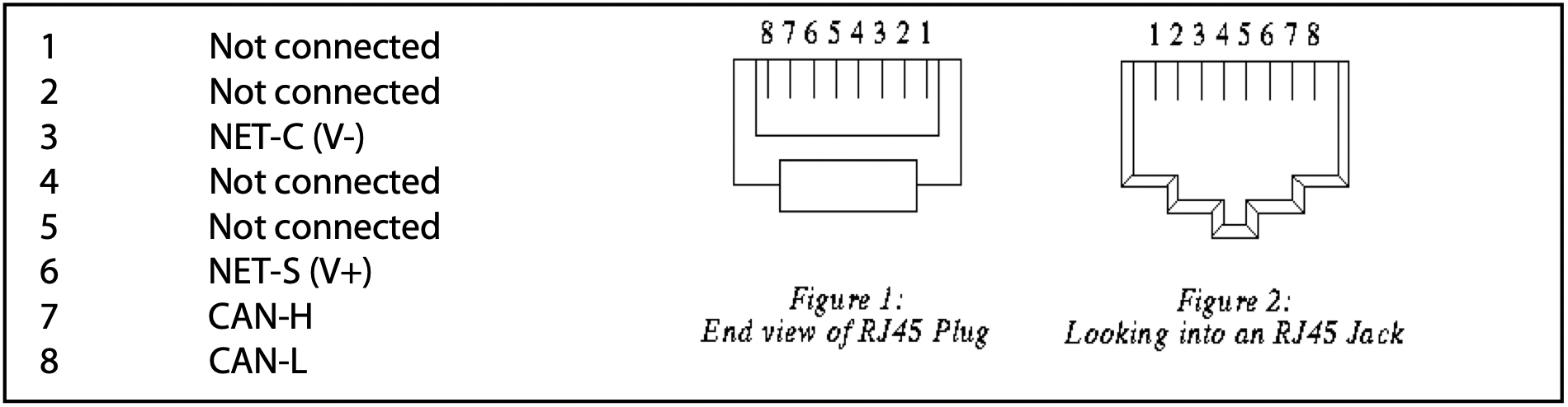 |
Victron VE.Can pinout
16.5.2. Installation and configuration
Route the cable from the Garnet panel to the GX device.
Ensure both the Garnet panel and GX device are powered off.
Connect the RJ45 plug to the VE.Can port of the GX device and the other end of the adapter cable to the Garnet panel.
Check bus termination:
For the GX device, use the supplied blue VE.Can RJ45 terminator.
Proper termination is mandatory, especially if the Garnet SeeLevel is the only RV-C device on the bus.
Once everything is connected, power on both devices.
Complete the setup by following the steps in the RV-C Configuration chapter section to configure the VE.Can port for the RV-C profile.